Ad: PCBWay manufactured and assembled the boards for this project free of charge and also supported the video. Some PCBWay links are affiliate links.
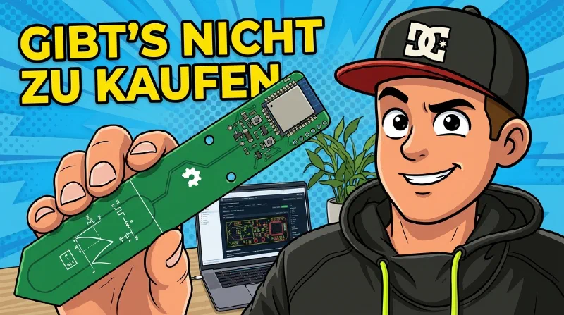
For me, the b-parasite is the best soil moisture sensor there is – and you can’t buy it anywhere. No manufacturer, no shop. There’s only a blueprint, free on GitHub. I had ten of them made, and here I’ll show you the whole journey: from the blueprint to the flower pot.

The video is in German with English subtitles.
What is the b-parasite?
The b-parasite is an open hardware project: a PCB whose lower half works as a capacitive soil moisture sensor. It also carries a temperature and humidity sensor (SHTC3) and a phototransistor for brightness.
At its heart is a Nordic nRF52840 in an E73 radio module. Unlike the usual ESP controllers it has no Wi-Fi, but Bluetooth Low Energy – which makes it extremely power-efficient. A single CR2032 coin cell lasts for many months.
The firmware transmits using the BTHome v2 standard, which Home Assistant understands without any extra integration.
Getting to a finished sensor takes four steps:
- Have the board manufactured and assembled
- Flash the firmware
- Set up a Bluetooth gateway for Home Assistant (e.g. a Shelly)
- Coat the board against moisture
Step 1: Ordering the board – no KiCad skills required
I can’t use KiCad, and faced with an order form of 30 options – copper weight, solder mask, surface finish – I wouldn’t know what to pick. For this project you don’t need to: the author has published the design on PCBWay as a Shared Project. Open the page, choose the quantity, order. No Gerber files, no manufacturing options.
My recommendation: add the assembly service (PCB+Assembly). The SMD parts are only millimetres in size – not something you just solder yourself – and you don’t have to buy them separately.
- Lead time: Manufacturing alone takes only a few days. With assembly, it took two to three weeks including shipping in my case.
- Approval photos: Before final soldering, PCBWay sends photos of the assembled boards. Since polarity matters for some parts, comparing them with the reference photo is worth it.
- The author earns too: With a Shared Project, the author gets a small share of every order. That’s why I deliberately link his project instead of creating my own.
If you’d rather support my channel, you can order via my PCBWay link (affiliate link).
Pitfall: no voltage at the battery pad
First coin cell in – and nothing happened. No LED, no Bluetooth. The multimeter showed a perfectly good cell, but hardly any voltage reached the board.
Looking into the battery holder from the side revealed small bumps on the large battery pad – enough to keep the coin cell from sitting flat. Together with PCBWay support, who responded very quickly, the cause was clear: residue from the production process.
Fix: Carefully rough up the pad once with very fine sandpaper. After that, battery power works.
Step 2: Flashing the firmware with an ESP32
The author provides precompiled firmware in the releases. For the assembled hardware version 2.0.0 you need:
blinky_nrf52840_2.0.0.hex– test firmware, the LED blinksble_nrf52840_2.0.0.hex– the actual sensor firmware (BTHome)
The nRF52840 is programmed via SWD. Professional programmers are expensive – the cheaper route is the open-source project ESP32_nRF52_SWD, which turns an ESP32 into an SWD flasher with a web interface. It was written by the same developer behind the OpenOBI firmware.
Wiring according to the project:
| b-parasite (nRF52) | ESP32 |
|---|---|
| SWDCLK | GPIO 21 |
| SWDIO | GPIO 19 |
| GND | GND |
| VCC | 3V3 |
Two rules before you start:
- Only one power source: either the coin cell or the 3.3 V from the ESP32 – never both at the same time.
- Erase first: The flasher doesn’t erase memory automatically. Run Erase before flashing.
I always flash in two steps: first Blinky – if the LED blinks, wiring and contacts are fine. Then the BLE firmware. This saves troubleshooting time.
During upload a white window with an hourglass appears – that’s normal. It’s done when the inconspicuous message completed shows up.
Tip: convert HEX to BIN
The flasher accepts HEX uploads, but they take several minutes. HEX files are text-encoded and much larger than the actual data. As BIN (offset 0), the same content flashes in seconds – a real difference with ten boards.
| |
Did it work? Unlike Blinky, the BLE firmware doesn’t blink continuously – it’s meant to save power. After a reset the LED blinks twice, and the values then appear in Home Assistant.
Step 3: Adding it to Home Assistant
Home Assistant needs a Bluetooth gateway that receives BTHome packets. I use a Shelly Gen2 or newer:
- In Home Assistant, open the Shelly device and click the gear icon.
- Set the Bluetooth scanner mode to at least passive (active works too) and confirm.
- Wait for the sensor’s next measurement cycle – or briefly press the button on the board.
The b-parasite then shows up under discovered devices. Once added, it provides these entities:
- Soil moisture
- Temperature
- Humidity
- Illuminance
- Voltage and battery level
All ten of my boards worked right away.
Device called “E73…” instead of “b-parasite”? Some of my sensors first appeared under the radio module’s name. That’s purely cosmetic – all values arrive. You can rename the devices yourself; in my case Home Assistant eventually named them correctly anyway.
Step 4: Coating against moisture
The project wiki explicitly warns against putting the board into soil uncoated: moisture can creep under the solder mask and cause corrosion.
So I spray the lower half with a plastic-based protective coating: top side, 20 minutes to dry, flip, bottom side, another 20 minutes. A simple cardboard mask keeps the upper half with the electronics and battery holder free.
If you prefer something more enclosed, the repository also has 3D-printable cases. I think the bare boards look cooler – a matter of taste.
Hands-on test: how good are the readings?
Moisture percentage is not an absolute value
The percentage is not universally calibrated. The only certainties: dry in the air the sensor reads 0 %, in a glass of water 100 %. Everything in between depends on soil type, compaction, how the sensor sits and how moisture is distributed.
Over several weeks, though, you can nicely see the soil slowly drying out – and every watering as a steep rise. Just moving the sensor to a different spot in the pot changed my reading by about 10 percentage points.
For automations this means: don’t rely on a fixed threshold like “water below 20 %” – set the threshold individually per plant and sensor.
Battery life: extrapolation doesn’t work
The author mentions up to two years of runtime in the repository. Some of my sensors have been running since April and have lost about 18 mV of their initial voltage.
A linear extrapolation gave almost 23 years for one sensor and 0.8 years for another. Both are nonsense: a CR2032’s voltage doesn’t drop linearly. It stays almost flat for a long time and then falls off steeply at the end. Depending on where on that curve you measure, the extrapolation gives wildly different results.
A better approach is a Home Assistant trigger on a minimum voltage that reminds you to change the battery in time.
Radio gaps
The sensor transmits every 10 minutes. In my setup roughly every tenth packet didn’t arrive, and the biggest gap in the log was about an hour. For a plant sensor that’s no problem – soil doesn’t dry out in an hour.
Verdict: is it worth the effort?
If you only want to know whether your plant is thirsty: probably not. A ready-made sensor is less hassle – for example the Zigbee soil moisture sensor from my hands-on test.
But if you want a sensor that
- lasts a very long time on a coin cell,
- runs open firmware nobody can shut down,
- works fully locally – no cloud, app or account,
- and simply shows up in Home Assistant,
then for me the b-parasite is the best soil moisture sensor you can get. You just have to have it built.
The effort in concrete terms:
| Step | Effort |
|---|---|
| Ordering and waiting | 2–3 weeks, hardly any work |
| Flashing | about 1–2 hours for ten devices |
| Coating | about 30 minutes for the whole batch |
Giveaway: 3 b-parasite sensors
I’m giving away three sensors from this batch. To enter: like the video on YouTube, subscribe to the channel and reply under the pinned comment explaining why you’d like to win one.
Links
- b-parasite on GitHub (repository, wiki, releases, cases)
- b-parasite Shared Project on PCBWay – commission goes to the author
- ESP32_nRF52_SWD – SWD flasher for nRF52
- BTHome integration in Home Assistant
Ad: PCBWay manufactured and assembled the ten boards and supported the video. I earn a commission via my PCBWay link at no extra cost to you. PCBWay had no influence on the content of this article.
Note: Links marked with affiliate link are affiliate links. As a partner of various retailers and manufacturers (e.g. Amazon, OBI via the Awin network, Shelly) I earn from qualifying purchases. This means I receive a small commission if you purchase through these links — at no extra cost to you. The revenue helps me run this blog and YouTube channel and keep creating content. Thank you for your support!
― Joachim