My doorbell is a completely normal, old Siedle intercom handset. No WiFi, no app, no cloud. And yet it pings my phone whenever someone rings — and I can open the door straight from Home Assistant. Here’s the catch: I’m not the only one on this system — four neighboring apartments in this building hang off the very same wiring. One wrong move, and I take down the whole building’s intercom. That’s exactly why I’m showing you here how to make any doorbell smart without bothering your neighbors — and the trick is simpler than you might think.
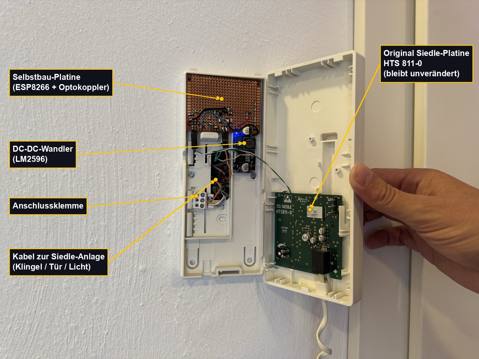
Safety note: Working on an intercom system is at your own risk. The terminals carry both DC and AC voltages — always work de-energized, measure your own values, and never load the bus line directly. In multi-party buildings, a single mistake can disturb every neighbor’s system — which is why galvanic isolation via an optocoupler isn’t a nice-to-have here, it’s mandatory.
Why not just buy a ready-made solution?
Roughly every second intercom system in Germany is made by Siedle — so there’s a good chance you have one too. And if you don’t, the principle still carries over. Of course there are off-the-shelf solutions: the Nuki Opener, for example, is wired in parallel to the system and can then open the door. That means locking yourself into the Nuki and app ecosystem, needing an extra battery, and spending around €100. Or the official Siedle solution, the Siedle IQ HTS — that replaces the intercom handset entirely and hooks into the Siedle app. An expensive full swap, and you’re stuck in the manufacturer’s cloud.
Both work. But both mean depending on a manufacturer, a cloud that has to keep running, and handing over control. I wanted the opposite: a robust, local solution that still works in ten years — one no vendor can pull the plug on. So I built it myself.
The principle in one sentence
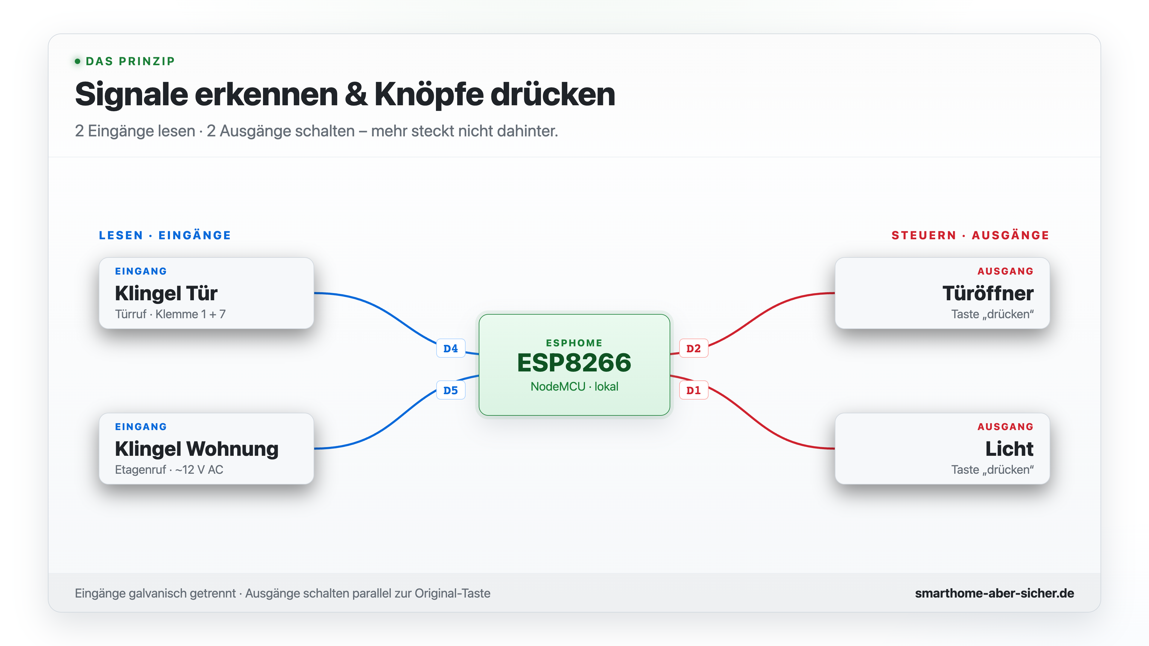
And here comes the single most important sentence of this whole project: you don’t need to understand the entire system — and you definitely don’t need to reverse-engineer the bus protocol. You only need to do two things: find the right signal, and electronically “press” the buttons that are already there.
- Read (inputs): Is the front door ringing? Is the apartment door ringing?
- Control (outputs): everything you could already operate directly on the device itself — in my case, the door opener and the stairwell light.
There’s no more magic to it than that. Exactly what the ring signal looks like technically varies from system to system, but the approach stays the same. I’ll show it to you concretely using my Siedle system as the example (intercom handset HTS 811-0, 1+n technology).
Detecting the ring: the voltage trick
How does the ESP detect that it’s ringing? Through the voltage on the line. At rest, my system sits at around 18 volts. When the front door rings, the voltage briefly jumps to 24 volts, the ringtone plays, and it drops to about 15 volts. The circuit detects exactly this jump.
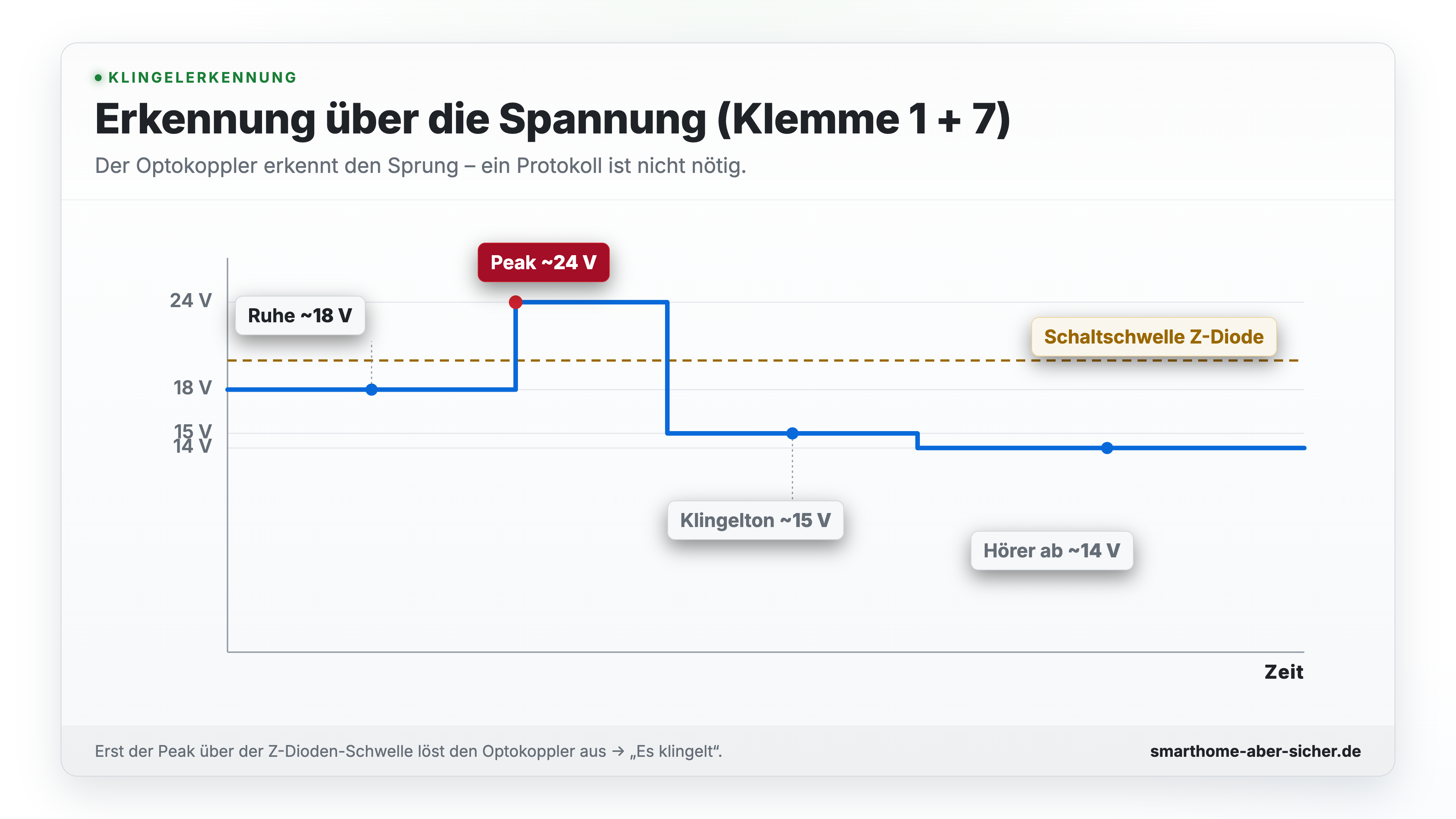
I measured these exact values on my own system myself — on a different 1+n installation, the absolute values may vary depending on the power supply type, cable length, number of subscribers, or age of the installation. But the basic behavior — a stable resting voltage, a short peak when it rings, and a drop during the ring tone — is, according to Siedle’s own system manual, characteristic of the entire 1+n series, so it applies to every Siedle device using this technology. More on that in a detailed thread on mikrocontroller.net and in the Siedle system manual.
The trick in the circuit: a Zener diode in front of the optocoupler. It makes sure nothing gets through at rest — only at the ring peak does the optocoupler switch through, and the ESP knows: it’s ringing. I even distinguish between two different rings: the front door, and the apartment door bell right in front of the flat, the so-called floor call. That runs over its own terminal with AC voltage, so there’s a second optocoupler for that.
Opening the door: press the button instead of rebuilding the protocol
Now it gets really interesting. With Siedle’s 1+n system, “door open” isn’t transmitted digitally at all — it’s sent as a tone frequency, a whistle tone around 20 kilohertz that’s modulated onto the line. The outdoor station at the front door listens in, recognizes exactly this frequency with a filter, and then switches the door buzzer. The light button does the same thing, just with a different frequency.
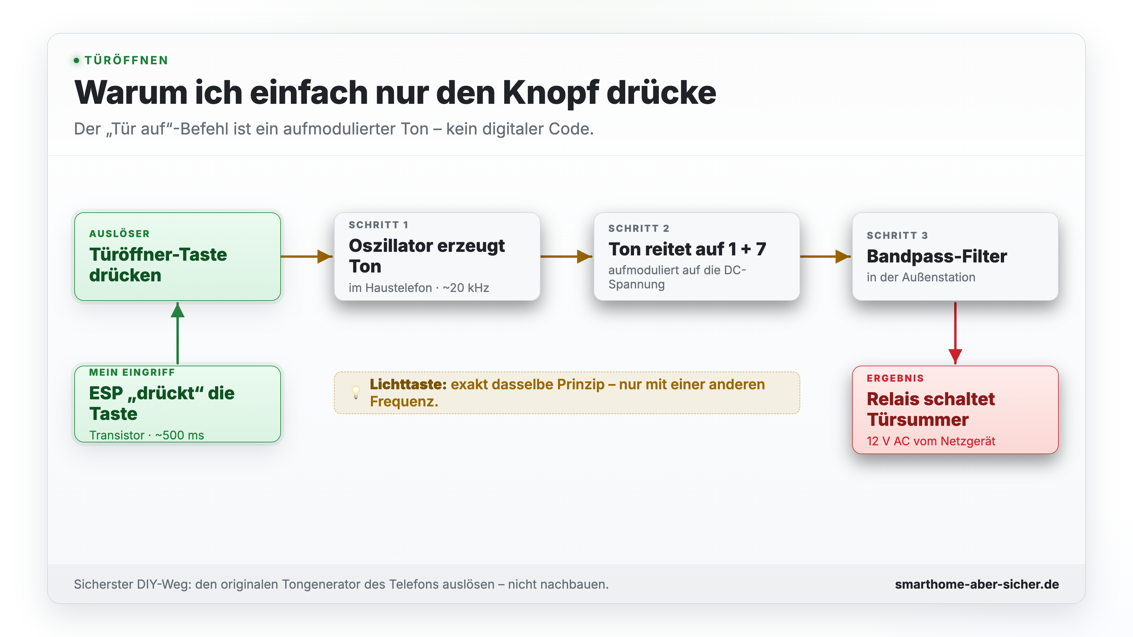
I could try to somehow recreate and inject that frequency myself. But that only makes things needlessly complex, and I’d risk disturbing the whole system again. So instead I do it the other way around — and this is really the key trick: I simply press the existing door-opener button with my ESP. It closes the button’s contacts for a brief moment, like an extra finger. The handset itself then generates the whistle tone on the line, all on its own. I don’t need to understand the frequency at all — I just press the button. And that’s been working reliably for months, even with the handset hung up.
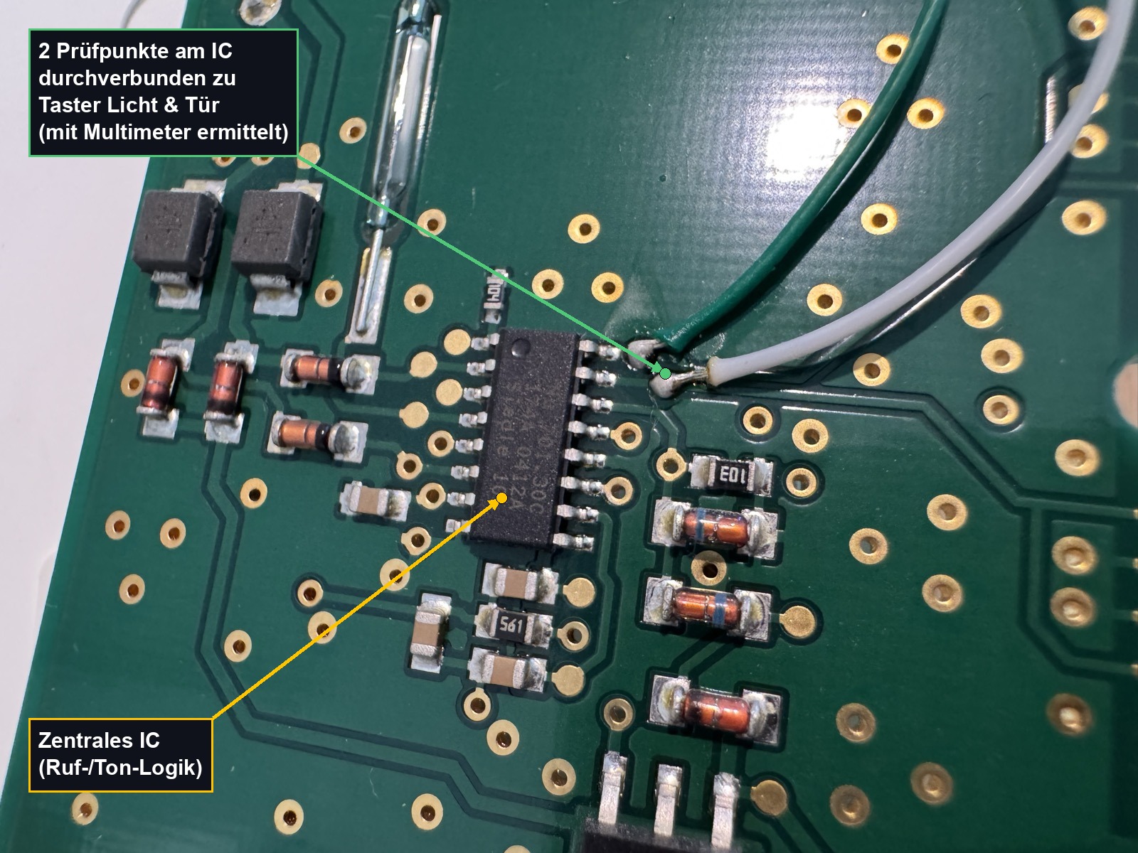
So I don’t damage the buttons while soldering, I don’t tap the signal directly at the buttons at all — instead, at two test points on the back of the circuit board that I found beforehand with a multimeter; they’re directly wired 1:1 to the buttons.
The hardware: compact and cheap
The hardware is pretty manageable: an ESP8266 NodeMCU as the microcontroller with WiFi, an LM2596 step-down converter that taps the ESP’s power supply straight from the system voltage — no extra power supply needed. Then there’s the coupling stage: optocouplers with resistors and a Zener diode for the two ring inputs, plus two transistors for the door-opener and light outputs. All soldered onto a small perfboard that fits easily inside the intercom handset’s housing — the original circuit board stays almost completely untouched right next to it.
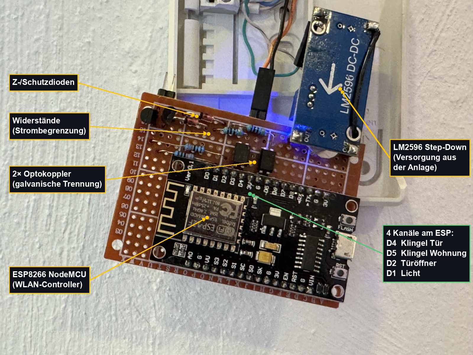
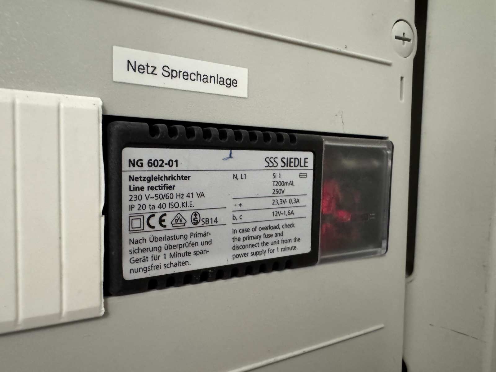
The whole system is fed from a central Siedle power rectifier down in the basement, which delivers around 23 volts for the bus and 12 volts for the door buzzer. The few milliamps I tap off for my ESP don’t disturb the other devices in the other apartments at all.
ESPHome: three details that matter day to day
The software is ESPHome — two binary_sensors for the two bells, two switches for the door opener and the light. Sounds like about twenty lines of YAML, and it is. But three details decide whether this thing actually runs reliably day to day:
inverted— the optocoupler pulls the pin to ground, so active means low, not high. Instead of changing that in hardware, it’s a single line of YAML — plus adelay_onfor debouncing, so a random glitch on the line doesn’t trigger a phantom ring.- The 500 ms pulse — the door opener isn’t a permanent switch, it’s a switch that turns itself back off. That’s not just a nice-to-have: if the WiFi drops out mid-action for whatever reason, the switch would otherwise stay on permanently and the door would stay open. The ESP simply counts down that half-second itself, completely without the network.
restore_mode+ pin choice —restore_modeis set to “always off,” so the ESP doesn’t restore the last state after a power outage and unintentionally open the door. And the door opener and light sit on D1 and D2 — on the ESP8266, the pins that are guaranteed to do nothing during boot. A few other pins do change state briefly at startup, and the door would buzz briefly on every restart if wired to one of those.
There’s one thing I’d do differently today: my bell is wired to pin D4, and D4 is also one of those special pins that has to be high during boot. As an input, it’s run problem-free for months for me — but if it rang in the exact second the ESP restarts, it wouldn’t boot. In practice that’s basically never happened, and I’m not going to re-solder it now — but if you’re building this yourself, use D5 or D6 for the bell instead.
The payoff: four entities in Home Assistant
In Home Assistant I now have four entities: front door bell, apartment bell, door opener, and light. From those I can build whatever I want — a push notification to my phone when it rings, manually opening the door from the dashboard or by voice command, or automatically opening the door when a visitor knows the secret ring signal and presses the bell in the right rhythm.
Conclusion: a question of proportionality
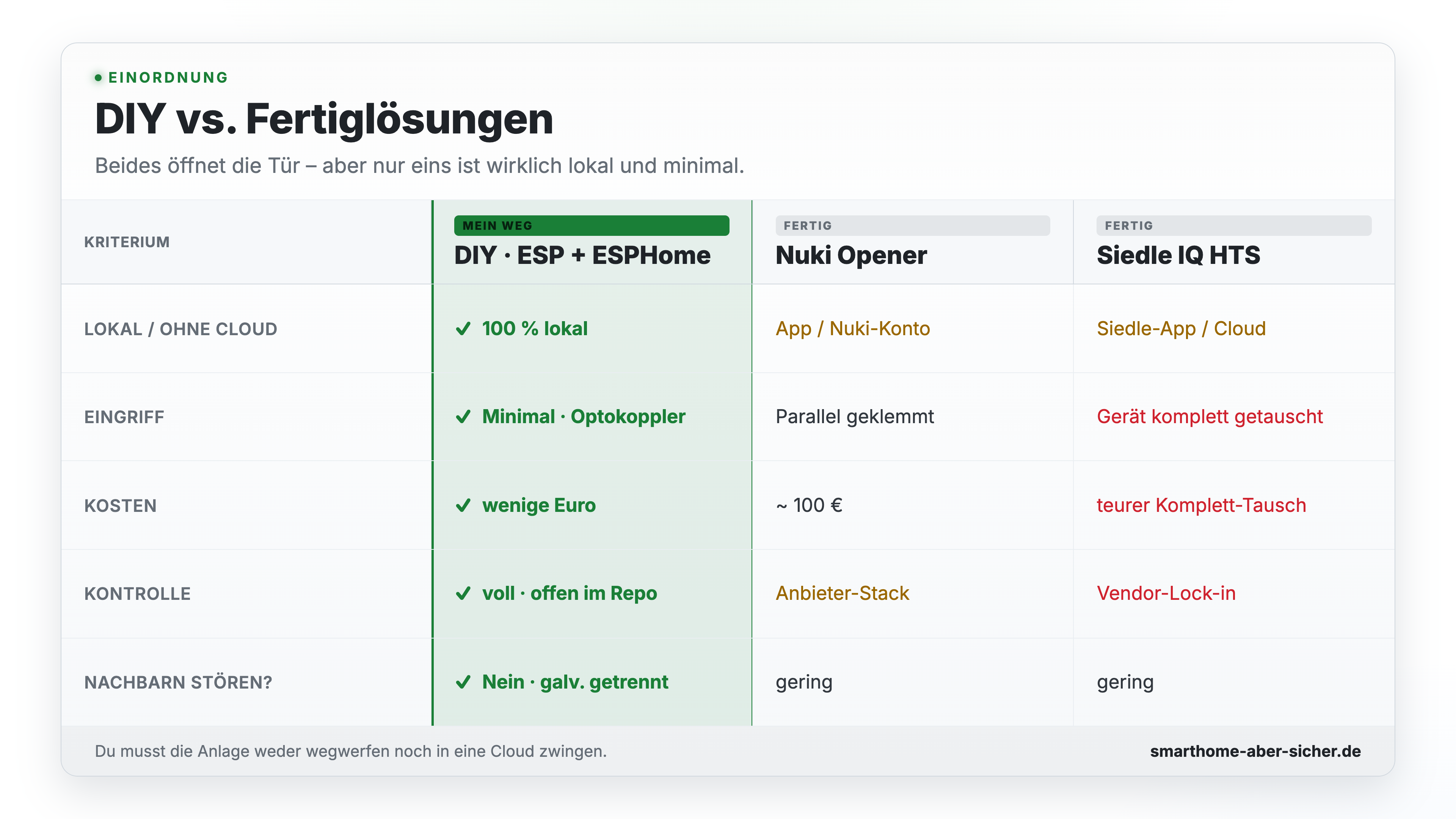
Off-the-shelf solutions like the Nuki Opener or the Siedle IQ HTS aren’t bad — they’re just a different answer to a different priority: convenience and manufacturer support in exchange for money and a bit of control. My approach is deliberately minimally invasive: no bus reverse-engineering, no cloud, no intervention that could endanger other apartments in the building. Just two signals to detect and two buttons to press electronically — galvanically isolated, reversible, and for well under €20 in materials.
GitHub repo
My complete ESPHome config, the documentation, the voltage graph, the circuit diagram, and the labeled photos of my system are all in the GitHub repo:
➡️ github.com/jowi24/siedle-hts-811-esphome
If you also have a Siedle 1+n system, you can dive straight in. If you have a different one, use this as a starting point for your own solution — the tricks in this article should get you there quickly.
Now it’s your turn
Is your doorbell smart yet? Have you built something yourself, or are you rebuilding my approach right now — whether with Siedle or another system? Let me know in the comments how you’d extend this, and what automations you use with your own intercom. Improvement suggestions and pull requests for the repo are always welcome.